 0
0


 0
0


1. Voltage follower
A voltage follower (also called a buffer) does not amplify or invert the input signal, but rather provides isolation between the two circuits. The input impedance is high and the output impedance is low, avoiding any load effects within the circuit. When the output is connected directly back to one of the inputs, the buffer has a total gain of +1 and Vout = Vin.

2. Amplifier inverter
The inverter, also called the inverting buffer, is the opposite of the previous voltage follower. If the resistors are equal, the inverter will not amplify, but will invert the input signal. The input impedance is equal to R and the gain is -1, giving Vout = -Vin

3. In-phase amplifier
In-phase amplifiers do not invert the input signal or generate an inverse confidence signal, but amplify it in a ratio of (RA+ RB) /RB or usually 1+ (RA/RB). The input signal is connected to the in-phase (+) input

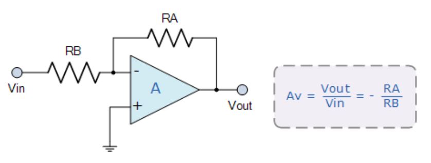
4. Inverting amplifier
The inverting amplifier inverts and amplifies the input signal simultaneously at the -RA/RB ratio. The gain of the amplifier is controlled by negative feedback using a feedback resistor RA, and the input signal is fed to the inverting (-) input.

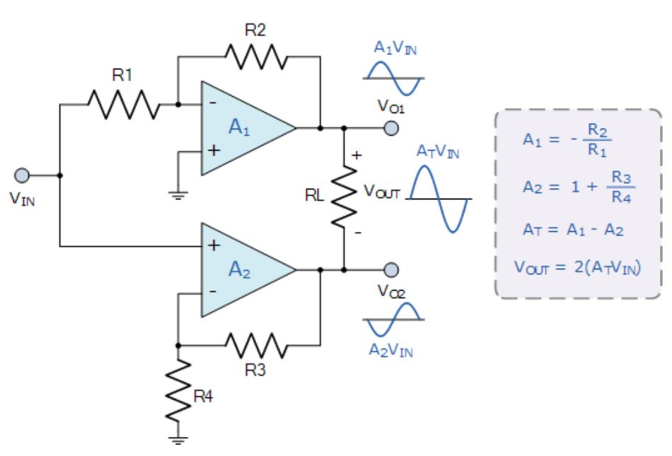
5. Bridge amplifier
The inverting and in-phase amplifier circuits above can be connected together to form a bridge amplifier configuration. The input signal is shared by the two opamps, and the output voltage signal is straddled at both ends of the load resistance R L, which floats between the two outputs.
If the two op-amp gains A1 and A2 are equal in size to each other, the output signal will be doubled because it is actually a combination of two separate amplifier gains.

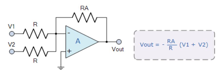
6. Voltage adder
The adder, also called a summing amplifier, produces an inverting output voltage proportional to the sum of the input voltages V1 and v2. More inputs can be summarized. If the values of the input resistors are equal (R1=R2=R), the total output voltage is the given value and the gain is +1. If the input resistances are not equal, the output voltage is a weighted sum and becomes: Vout =- (V1 (RA/R1) + V2 (RA/R2) + etc.)

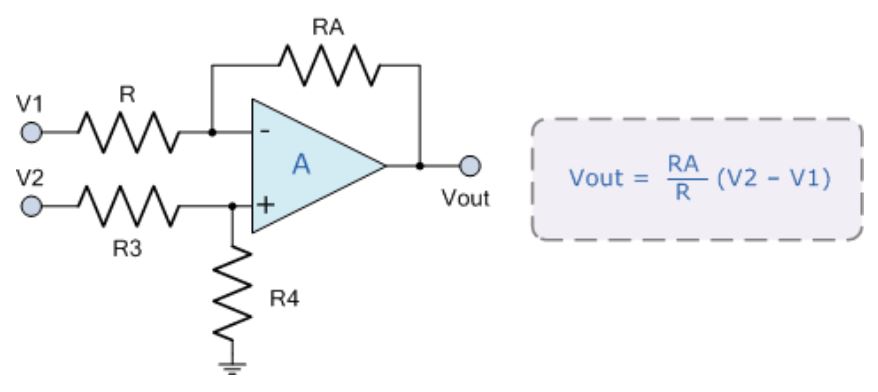
7. Voltage reducer
Also known as differential amplifiers, subtracters use inverting and in-phase inputs to produce an output signal, which is the difference between the two input voltages V1 and V2, thus allowing one signal to be subtracted from the other. If needed, you can add more input to subtract it.
If the resistances are equal (R=R3 and RA=R4), the output voltage is the given value and the voltage gain is +1. If the input resistance is unequal the circuit becomes amplifier when the difference V1 produces a negative output is higher than V2 and a positive output when V1 is lower than V2.

8. Voltage comparator
Comparators have many uses, but the most common is to compare the input voltage to the reference voltage, switching the output if the input voltage is higher than the reference voltage. If the input voltage is higher than the reference voltage set by the divider, the voltage is positive. If Vref is higher, the output will change state. When the input voltage drops below the preset reference voltage and Vin
