Post on April 3, 2023
Brushless direct current (BLDC) motors have been widely used in household appliances, industrial equipment and automobiles. While brushless DC motors offer a more reliable and maintainable alternative to traditional brushless motors, they require more sophisticated electronics to drive them. This article explores the many different technologies, sensor schemes, and popular algorithms used to drive brushless DC motors. A selection of motor driver ics from leading suppliers and suitable development and prototyping resources will also be introduced.
Brushless motor applications
Brushless DC motors have become so popular in the last decade that they are perhaps even more common than Wi-Fi, and you might be surprised to find these brushless DC motors whether you are in your home, office, or in a surrounding scene like your car. Allied Market Research estimates that by 2030, global Market brushless dc motor will be increased from $33.2 billion in 2020 to $72.2 billion (see figure 1), the 2030 BLDC motor Market Research report predicts, all rated power motor compound annual growth rate of 10.3%, Among them, 750 ~ 3000W brushless DC motor compound annual growth rate is the most significant.
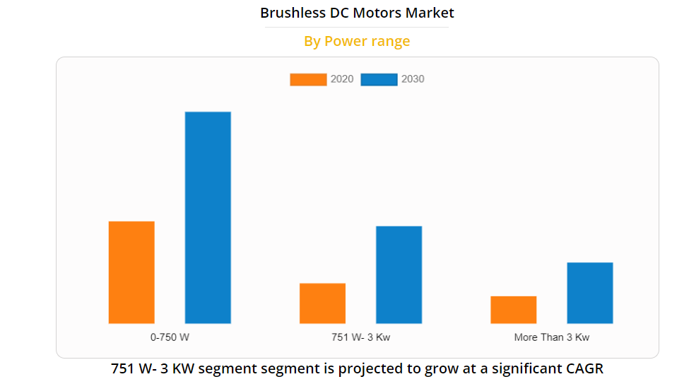
Figure 1:Allied Market Research (AMR) announces brushless DC motor market Growth Trends 2020 to 2030
Brushless DC motors are suitable for a variety of different applications, including battery-powered power tools, household vacuum cleaners, wireless remote-controlled drones and electric vehicles, as well as hundreds of industrial applications ranging from conveyor belts to production robots.
Brushless DC motors are popular due to their low maintenance characteristics, and they are also highly energy efficient, typically up to 92%, which is at least 10% to 15% higher than brushed motors of the same size. In addition, the BLDC is able to operate at much higher speeds because it doesn't have any brush friction. Brush removal also helps achieve a more compact size with lower audible noise and can significantly reduce EMI. These characteristics make them ideal powertrain parts for electric vehicles, where high torque and high-speed performance are critical.
However, the advantages of BLDCS need to be considered in conjunction with their higher cost and complex driver requirements. Figure 2 compares the different types of motor configurations that are popular and shows their advantages and disadvantages. Although brushless DC motors have slightly different operation and stator windings internal structure, they are very similar to permanent magnet synchronous motors (PMSM).
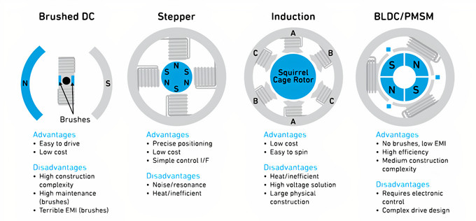
Figure 2:Used to illustrate the main advantages and disadvantages of the popular DC motor product types
How does brushless DC motor work?
Before exploring how BLDCS and PMSM work, let's briefly cover some basic motor terms:
(1)Windings: Windings are copper wire coils placed in the stator or rotor. They act as electromagnets to generate a magnetic field based on the direction of the current. The three windings of the brushless DC motor in Figure 2 can be connected in series to build a single-phase motor, or can be separately connected to build a three-phase brushless DC motor.
(2)Rotor: The rotor is the rotating part of a motor. The windings around the rotor receive energy through the brushed motor brush. In a brushless motor, the windings are on the stator and permanent magnets surround the rotor. There is a small air gap between the rotor and the stator.
(3)Stator: The stator is the non-rotating part of the enclosure motor. The stator pole of a brushed motor is shown in Figure 2. If compared to a BLDC, the stator in a BLDC contains non-rotating windings.
(4)Reversing: Rotation is achieved by changing the direction of the current in the winding.
(5)Back electromotive force: Back electromotive force is the electrical energy produced by the winding as it passes through a magnetic field. In the case of a brushless DC motor, the back electromotive force comes from a permanent magnet in the rotor, which can be used to induce the position of the rotor relative to the stator windings to drive the reversing process.
The difference between a permanent magnet synchronous motor and a brushless DC motor is mainly due to the shape of the stator windings and the resulting back electromotive force waveform characteristics (see figure below).
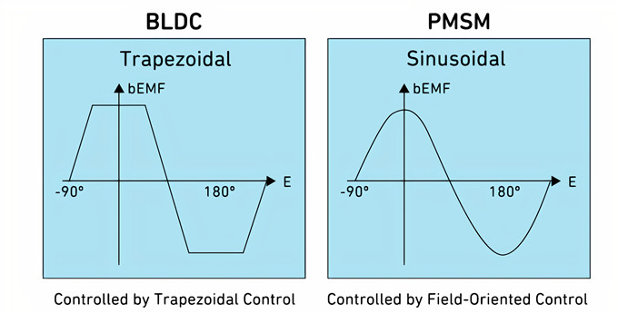
Figure 3:Comparison of back electromotive force waveform generated by BDLC and PMSM motors
Motor drive algorithms and sensors
To realize the rotation of a brushless DC motor or a permanent magnet synchronous motor requires reversing the drive signal applied to the stator winding. Motor driven controllers (often called drivers) based on semiconductor devices produce waveforms, the number and shape of which depend on the type of motor and the number of phases. As shown in Figure 3, compared with the sinusoidal method with field-oriented control (FOC) used by the permanent magnet synchronous motor, the brushless DC motor is suitable for the trapezoidal drive waveform. In three-phase PMSM, commutation utilizes three sinusoidal waveforms with phases 120 degrees apart from each other. BLDC motors can also be driven using sinusoidal waveforms.
Whether using FOC or trapezoidal drivers, effective rotor control requires accurate knowledge of the position of the rotor relative to the stator windings, which can provide important feedback to the motor drive for better control of motor speed and torque. Location information determines the sequence, time and frequency of driving signals.
There are two ways to determine rotor position: sensorless or sensorless.
Sensors: Hall effect sensors can be arranged next to each stator winding (see small blue squares in Figure 2) to detect changes in magnetic field polarity (N to S, S to N) as the rotor rotates. Each three-phase motor requires three sensors.
Sensorless: Sensorless methods use back electromotive force to determine rotor position instead of using sensors.
Both sensing methods have advantages and disadvantages. Hall Effect sensors involve additional component costs and more assembly time, but sensor sensing BLDC/PMSM motors provide excellent torque, smooth rotation and higher efficiency. The drive controller of permanent magnet synchronous motor is often more complex, and the use of FOC requires the use of sensors.
Sensorless methods are common in brushless DC motors, which can bring the motor to a relatively attractive low price, but require the algorithm to determine the rotor position based on the back electromotive force induced in the stator windings. One of the big challenges of sensorless BLDC motors arises at startup. Since there is no motion, there is no back electromotive force, so the rotor position must be calculated in a different way. Typically, high-frequency drive signals are fed to each phase winding and the position is calculated accordingly by a specific algorithm.

Figure 4: Simplified diagram of a three-phase BLDC motor in which the commutation process is created using a Hall effect sensor and the inverter operation is ordered
Figure 4 highlights a simple three-phase BLDC motor configuration using Hall effect sensors (HSW, HSV, and HSU). The sensor is basically a digital switch indicating the polarity of the detected magnetic field, with N equal to "1" and S equal to "0". The output of the three sensors is combined to give a 3-bit digital logic "opcode" that indicates the position and direction of the rotor as it changes. This information is the basis of the drive signal provided by the three-phase power transistor inverter stage. For relatively low power BLDC applications, the sensor interface, motor controller, and drive transistor are usually integrated in a single controller IC. High power motors typically use a grid drive output from the controller IC and a power MOSFET equipped with a radiator to achieve the required drive current.
To change the speed of the motor, the duty cycle, the pulse on/off ratio, can be changed using PWM technology. This method can limit the starting current, so it also provides a great advantage when used during motor startup.
BLDC motor driver IC and development resources
Figure 5 shows the functional block diagram of a low power senserless three-phase BLDC motor driver TI DRV10963. The IC contains three power mosFeTs suitable for BLDC motors up to 5V/0.5A and can be used to drive cooling fans used on laptops and high performance processors. With short circuit and overcurrent protection, the DRV10963 monitors the current and voltage of each MOSFET via a multiplex analog-to-digital converter (ADC). The PWM input can be used to control and achieve the desired motor speed. The "FR" input allows the motor to change direction at startup, and the "FG" output provides motor speed information.
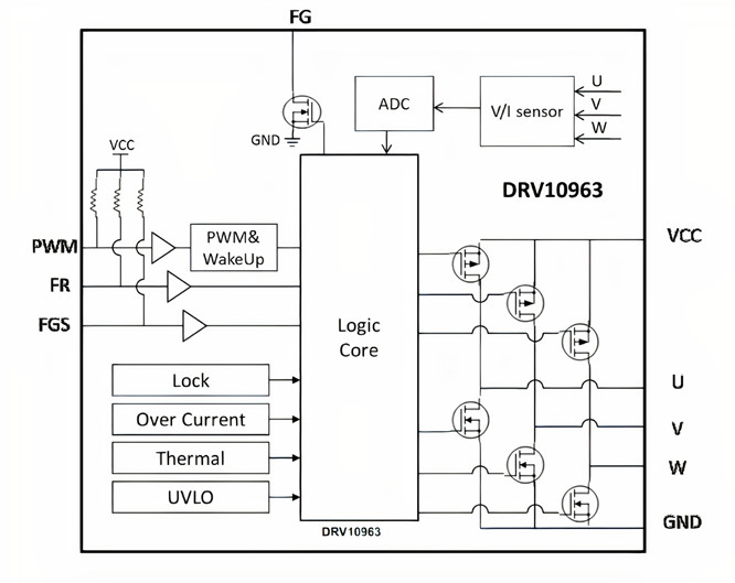
Figure 5: Functional block diagram of TI DRV10963 5V three-phase Sensorless BLDC motor driver
Microchip offers a comprehensive line of single-chip BLDC motor drivers and grid driver ics, one of which is the MCP8063, a three-phase brushless sinusoidal sensorless motor driver designed for automotive cooling fans and a variety of pump applications.
The Qorvo PAC5532 Power controller is suitable for a wide range of high-speed consumer products, industrial and automotive motor control applications, including battery-powered power tools, electric bicycles and lightweight hybrid electric vehicles. The PAC5532 is suitable for 48-120VDC systems and has an integrated 150MHz Arm Cortex-M4F 32-bit kernel with full and configurable power management and driver capabilities (see Figure 6).
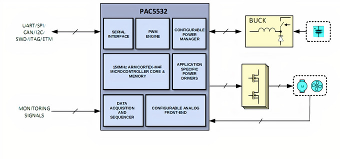
Figure 6: Simplified configuration block diagram of Qorvo PAC5532 for battery powered motor control applications
The Qorvo PAC5532EVK1 evaluation Kit provides complementary support for PAC5532.

Figure 7 lists the major components of the evaluation suite, including PAC5532 and the three-phase half H-bridge inverter assembly
Another motor control IC is the high performance Renesas RA6T2 microcontroller family. The IC is based on a 240MHz Arm Cortex-M33 microcontroller kernel and includes a hardware-based accelerator for accelerating complex motor control algorithms and running secure encryption features. It also incorporates a very complete set of analog capabilities, including a 12-bit analog-to-digital converter (ADC), a 12-bit analog-to-digital converter (DAC), programmable gain amplifiers, and high-speed comparators (see Figure 8).

Figure 8: Functional block diagram of motor controller based on Renesas RA6T2 microcontroller
Renesas MCK-RA6T2 Evaluation Kit provides a convenient and practical prototyping method for brushless motor driver designs. The kit includes three connection boards: inverter board, microcontroller board and communication board. It also includes a small brushless DC motor as well as all the necessary cables. The functional architecture of MCK-RA6T2 is shown in Figure 9.

Figure 9: Functional block diagram of the Renesas MCK-RA6T2 Brushless Motor evaluation kit
 0
0


 Login/Register
 BOM
BOM
 Cart
Cart

