BCP53 Introduction
The BCP53 is a PNP silicon epitaxial transistor for audio amplifier applications. It’s designed for high current handling and moderate voltage capabilities, making it ideal for driving loads like small motors, relays, or LEDs. With its SOT-223 package, the BCP53 provides efficient thermal performance in a compact form, suited for space-constrained designs.
BCP53 Pinout

Pin 1 (Base): Controls current flow between collector and emitter; a small base current controls a larger current through collector-emitter.
Pin 2 (Collector): Main current path in a PNP transistor, where current flows out.
Pin 3 (Emitter): Entry point for current in a PNP transistor, usually at a higher voltage.
Tab (Collector): Acts as an additional collector connection, aiding in heat dissipation for medium-power applications.
BCP53 Working Principle
The BCP53 transistor operates based on the principle of current amplification. As a PNP bipolar junction transistor (BJT), it consists of three layers: the emitter, base, and collector. In the BCP53, the majority charge carriers are holes, which move from the emitter to the collector when a small current is applied to the base. When a negative voltage is applied to the base relative to the emitter, the transistor switches on, allowing a larger current to flow from the emitter to the collector.
BCP53 Symbol

BCP53 Footprint

BCP53 3D Model

BCP53 Marking Diagram

BCP53 Specification
| Parameter |
Value |
| Voltage - Collector Emitter Breakdown |
80 V |
| Collector-Base Voltage |
100 V |
| Emitter-Base Voltage |
5 V |
| Vce Saturation (Max) @ Ib, Ic |
500mV @ 50mA, 500mA |
| Current - Collector (Ic) |
1.2 A |
| Current - Collector Cutoff (Max) |
100nA (ICBO) |
| DC Current Gain (hFE) (Min) @ Ic, Vce |
40 @ 150mA, 2V |
| Power - Max |
1.5 W |
| DC Current Gain |
40 - 250 |
| Transition Frequency |
100 MHz |
| Operating Temperature Range |
-55°C ~ 150°C |
| Package Type |
SOT-223 |
BCP53 Features
High Current: 1.5 Amps
NPN Complement is BCP56
he SOT‐223 Package can be soldered using wave or reflow. The formed leads absorb thermal stress during soldering, eliminating the possibility of damage to the die
Device Marking:
BCP53T1 = AH
BCP53-10T1 = AH-10
BCP53-16T1 = AH-16
Pb-Free Packages are Available
BCP53 Applications
Audio Amplifiers
Signal Processing
Power Management
General Switching Applications
DC-DC Converters
LED Drivers
Battery-Powered Devices
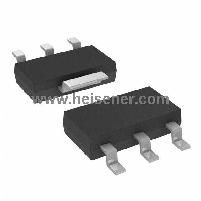
BCP53 Package
The BCP53 transistors are available in the SOT-223 package, a package design for mid-power surface mount applications.The SOT-223 package has a low thermal resistance, which aids in heat dissipation. The package is constructed primarily of plastic with a metal heat sink. Due to the structural characteristics of the SOT-223, the BCP53 can withstand high currents. In addition, the SOT-223 package has a clean and easy-to-solder pin arrangement, making it ideal for automated production and SMD mounting.

How to Use BCP53?
To use a BCP53 transistor, you can follow the steps below:
Step 1: First, determine the purpose of the BCP53 transistor in the circuit based on the circuit requirements. Then, connect the base (Pin 1) of the transistor to the control voltage source, the collector (Pin 2) to the load, and the emitter (Pin 3) to the higher supply voltage. In a PNP configuration, current flows from the emitter to the collector, so the emitter should be connected to a higher potential than the base.
Step 2: Apply some base current. The larger collector-emitter current is controlled by applying an appropriate negative voltage between the base and emitter. A resistor can be used to limit the base current during this process. The amount of base current will determine how much the transistor conducts, which in turn controls the current flow between the collector and emitter.
Step 3: Once the connections are complete, power up and test the circuit. Observe that the output current meets the design requirements, and if adjustments are needed, optimize the collector current by varying the base current.
FAQs
What is the BCP53 transistor used for?
The BCP53 is primarily used in audio amplifier applications and for switching purposes in various electronic circuits. Its PNP configuration makes it suitable for applications that require current amplification.
Can I use the BCP53 in high-frequency applications?
The BCP53 is designed for medium power applications and may not perform well in high-frequency applications. For such cases, consider using transistors specifically rated for high-frequency operations.
How should I handle the BCP53 during installation?
When handling the BCP53, it's essential to avoid electrostatic discharge (ESD). Use appropriate ESD protection measures, such as wrist straps and grounded work surfaces, to prevent damage to the transistor.
Are there any alternatives to the BCP53?
Yes, alternatives to the BCP53 include other PNP transistors with similar specifications, such as the BCP55 or BCP56.
 0
0


 Login/Register
 BOM
BOM
 Cart
Cart