DS12C887 Principle
The DS12C887 is a real-time clock (RTC) chip which provides essential timekeeping functions, including a real-time clock/calendar, one time-of-day alarm, three maskable interrupts with a common interrupt output, a programmable square wave, and 113 bytes of battery-backed static RAM. Notably, the DS12C887 adds a century byte at address 32h, which is used to keep track of centuries in date calculations. The device automatically adjusts the date at the end of the month for months with fewer than 31 days and corrects for leap years. It operates in either 24-hour or 12-hour format with an AM/PM indicator.
The working principle of the DS12C887 revolves around its ability to maintain accurate timekeeping even during power failures. A precision temperature-compensated circuit monitors the status of the primary power supply (VCC). If a power failure is detected, the device automatically switches to a backup supply, such as a connected lithium coin-cell battery. Additionally, the DS12C887 is accessed through a multiplexed byte-wide interface, supporting both Intel and Motorola modes.
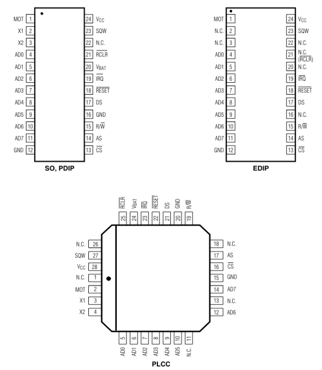
DS12C887 Pinout
DS12C887 CAD Models
Symbol

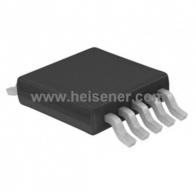
Footprint

3D Model

DS12C887 Operating Circuit

DS12C887 Functional Diagram

DS12C887 Features
- Binary or BCD time representation
- Daylight saving time option
- Interfaced with software as 128 RAM locations
- 14 bytes of clock and control registers
- 114 bytes of general-purpose, battery-backed RAM
- Interrupt output with three independently
- Maskable interrupt flags
- Time-of-day alarm once per second to once per day
- Periodic rates from 122μs to 500ms
- End-of-clock update cycle flag
- Programmable square-wave output
- Automatic power-fail detect and switch circuitry
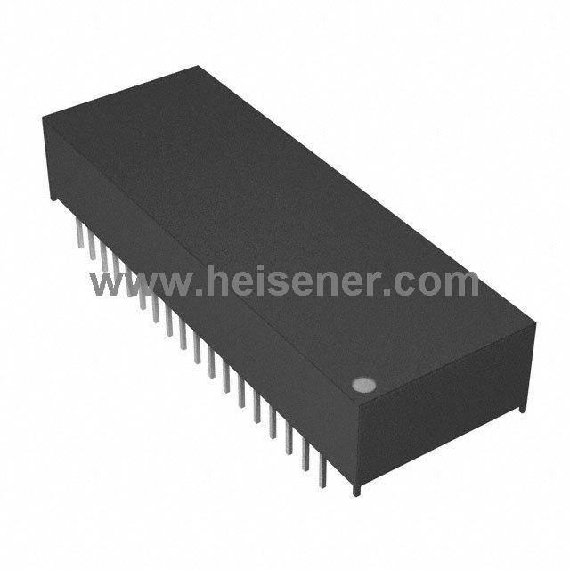
- Optional encapsulated DIP (EDIP) package with integrated crystal and battery
- Optional industrial temperature range available
- Underwriters Laboratory (UL) recognized
DS12C887 Applications
Computers and Servers
Embedded Systems
Industrial Control Systems
Telecommunications Equipment
Consumer Electronics
Medical Devices
Security Systems
Data Loggers
Network Hubs, Bridges, and Routers
DS12C887 Specifications
| Specification |
Details |
| Clock Functions |
Real-time clock/calendar, century byte, alarm, maskable interrupts |
| Static RAM |
113 bytes battery-backed RAM |
| Package Type |
24-pin DIP |
| Backup Supply |
Lithium coin-cell battery |
| Operating Voltage (VCC) |
4.5V - 5.5V |
| Backup Voltage (VBAT) |
2.0V - 3.7V |
| Operating Temperature Range |
0°C - 70°C |
| Timekeeping Accuracy |
±1 minute per month at 25°C |
| Alarm Functions |
Time-of-day alarm |
| Memory Size |
113B |
| Square Wave Output |
Programmable frequency |
| Date Format |
YY-MM-DD-dd |
| Time Format |
HH:MM:SS (12/24 hr) |
| Interface |
Parallel |
| Century Byte Address |
32h |
| Mounting Type |
Through Hole |
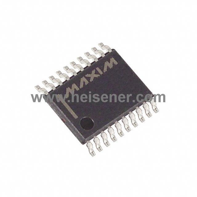
DS12C887 Manufacturer
The DS12C887 real-time clock (RTC) is manufactured by Maxim Integrated, which is now a part of Analog Devices, Inc. Maxim Integrated provides high-performance semiconductor products, including integrated circuits for various applications such as power management, interface, and communications, which offers high-quality products and reliable service for grobal customers.
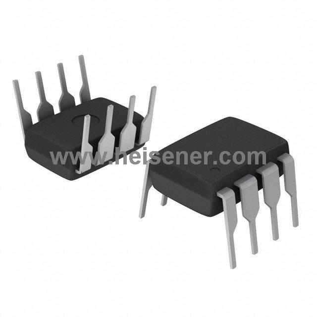
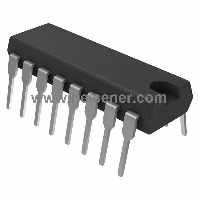
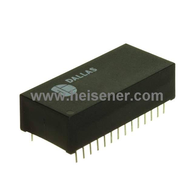
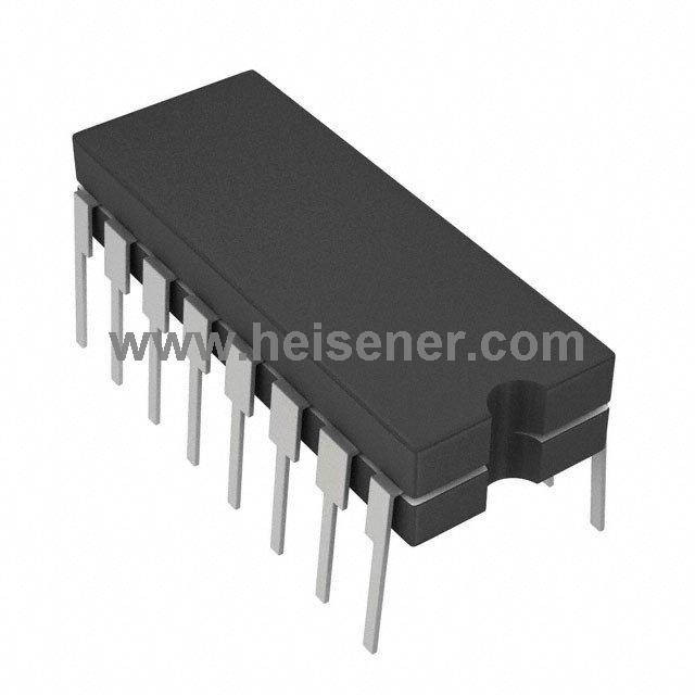
DS12C887 Package
The DS12C887 real-time clock (RTC) is housed in a 24-pin Dual In-line Package (DIP), which features 24 pins spaced 0.1 inches apart, making it compatible with standard breadboards and sockets. The package dimensions typically follow industry standards for 24-pin DIPs, with a length of approximately 1.25 inches (31.75 mm), a width of 0.3 inches (7.62 mm), and a height suitable for fitting into compact electronic assemblies.
How to Use DS12C887?
To start, connect the RTC's power supply pins, VCC and GND, ensuring a stable primary power source. For backup power, connect a lithium coin-cell battery to the VBAT pin, which allows the RTC to maintain time and date information during power failures.
Then initialize the DS12C887. This involves setting the control registers to configure the desired timekeeping and alarm functions. You need to write the initial date and time values to the appropriate RTC registers, considering the device supports both 24-hour and 12-hour formats with an AM/PM indicator. To access the RTC registers, use the multiplexed address/data bus, selecting the desired register by setting the address latch enable (ALE) signal, and then reading from or writing to the data bus.
To read the current time and date, continuously poll the RTC registers or set up periodic interrupts. The DS12C887 can generate three types of maskable interrupts: time-of-day alarm, periodic, and update-ended interrupts, all sharing a common interrupt output.
FAQs
How does the DS12C887 maintain time during a power failure?
The DS12C887 automatically switches to a backup power source, such as a connected lithium coin-cell battery on the VBAT pin, when it detects a primary power failure. This ensures continuous timekeeping even when the primary power is lost.
What are the primary functions of the DS12C887?
The DS12C887 offers real-time clock/calendar functions, one time-of-day alarm, three maskable interrupts, a programmable square wave output, and 113 bytes of non-volatile static RAM for storing user data.
How does the DS12C887 handle leap years and month-end date adjustments?
The DS12C887 automatically adjusts the date at the end of the month for months with fewer than 31 days and includes corrections for leap years.
Can the DS12C887 generate interrupts?
Yes, the DS12C887 can generate three types of maskable interrupts: time-of-day alarm, periodic, and update-ended interrupts, all of which share a common interrupt output.
 0
0


 Login/Register
 BOM
BOM
 Cart
Cart