TIP122 Introduction
The TIP122 is a NPN Darlington transistor, commonly used for high-power switching and amplification applications. It consists of two NPN transistors connected in a Darlington configuration, which means the current amplified by the first transistor is further amplified by the second one. This configuration provides a high current gain (typically 1000 or more), allowing the TIP122 to control large currents with a relatively small input current.
The operating principle of the TIP122 is based on the Darlington pair's ability to achieve a high current gain. When a small base current is applied to the TIP122, it turns on the first transistor, which amplifies the current and drives the second transistor. This results in a much larger current flowing from the collector to the emitter, allowing the TIP122 to switch or amplify loads up to 5A with a voltage rating of up to 100V.
TIP122 Pinout

TIP122 Features
- Gain around 1000, amplifying small base current to large collector current.
- Handles up to 100V collector-emitter voltage .
- Supports continuous collector current up to 5A.
- Composed of two NPN transistors for high efficiency.
- Built-in anti-parallel diode.
- Capable of dissipating up to 65W of power.
- Exhibits a low collector-emitter saturation voltage of 2V at 3A.
TIP122 Applications
Motor Drivers: Used to control and drive motors in various applications.
Relay Drivers: Ideal for switching relays in control circuits.
Power Regulators: Employed in power regulation circuits.
Amplifiers: Used in audio and signal amplification circuits.
Lighting Control: Suitable for dimming and controlling high-power lighting systems.
Industrial Automation: Applied in industrial control systems for driving high-power actuators and solenoids.
Battery Chargers: Used in battery charging circuits to control charging currents efficiently.
Solar Power Systems: Implemented in solar inverters and controllers.
Heater Control: Used to regulate current in heating elements in temperature control systems.
TIP122 CAD Model
Symbol
Footprint

3D Model

TIP122 Circuit

TIP122 Specifications
| Parameter |
Value |
| Collector-Emitter Voltage |
100 V |
| Collector-Base Voltage |
100 V |
| Emitter-Base Voltage |
5 V |
| Collector Current |
5 A |
| Base Current |
120 mA |
| Power Dissipation |
65 W |
| DC Current Gain |
1000 (min) |
| Collector-Emitter Saturation Voltage |
2 V @ 3 A |
| Operating Junction Temperature |
-65 to +150 °C |
| Thermal Resistance Junction to Case |
1.67 °C/W |
| Thermal Resistance Junction to Ambient |
62.5 °C/W |
| Transition Frequency |
3 MHz |
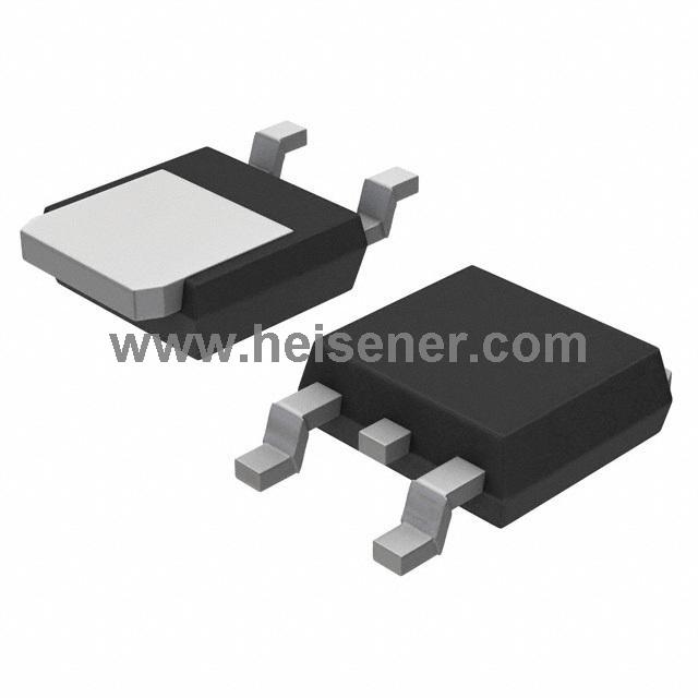
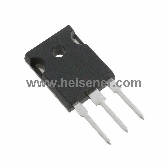
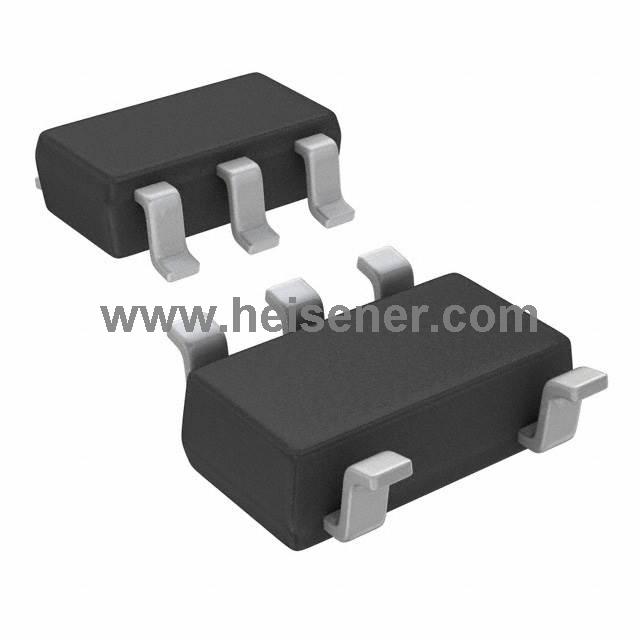
| Package |
TO-220 |
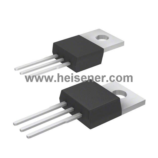
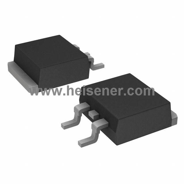
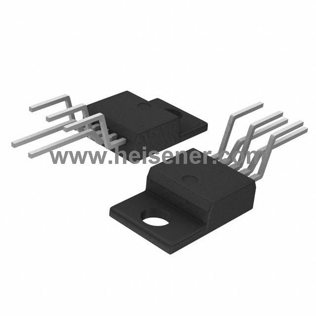
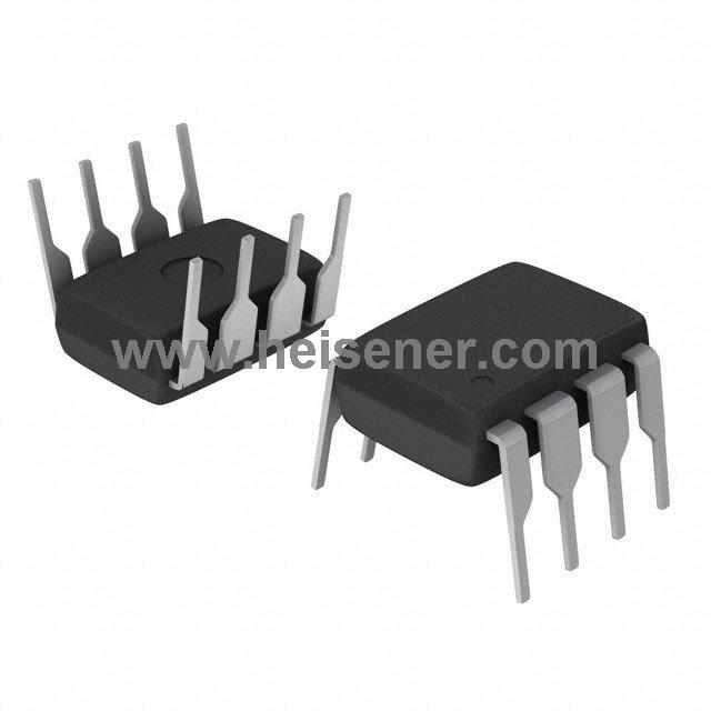
TIP122 Package
The TIP122 transistor is housed in a TO-220 package, which is a widely used and durable through-hole package. This package features three leads—Base, Collector, and Emitter—spaced with a standard 2.54 mm pitch, making it easy to integrate into various circuit boards. The TO-220 package dimensions are 10.16 mm in width, 15.75 mm in length, and 4.83 mm in height, with a lead length of 14.5 mm. It is designed to be mounted on a heat sink, significantly improving thermal management. It boasts a thermal resistance of 1.67 °C/W from junction to case.

TIP122 Manufacturer
The TIP122 transistor is produced by STMicroelectronics, which is one of the leading semiconductor manufacturers. The company designs, develops, and manufactures a wide range of semiconductor products, including microcontrollers, sensors, power management devices, and transistors, etc.
How to Use TIP122?
Identify the Pin Configuration: The TIP122 has three pins: Base (B), Collector (C), and Emitter (E). The pinout is typically (left to right): Base, Collector, Emitter when viewed from the front with the metal tab at the back.
Connect the Base Resistor: To control the TIP122, a current-limiting resistor is connected to the Base pin. Calculate the resistor value based on the desired base current and input voltage .
Connect the Collector Load: The load (e.g., a motor, relay, or light) is connected between the Collector pin and the positive supply voltage. Ensure the load current does not exceed the maximum collector current rating of 5A.
Connect the Emitter to Ground: The Emitter pin is connected directly to the ground of the circuit.
Apply the Input Signal: Provide the control signal to the Base pin through the base resistor. This signal determines when the TIP122 will turn on (conduct) or off (non-conductive).
Ensure Proper Heat Dissipation: Attach a heat sink to the TIP122 if the load current is high to manage heat dissipation effectively.
TIP122 Equivalents
| Transistor |
Type |
Voltage Rating (V) |
Current Rating (A) |
Configuration |
| TIP120 |
NPN Darlington |
60 |
5 |
Darlington |
| BD679 |
NPN Darlington |
80 |
4 |
Darlington |
| TIP41C |
NPN Power |
100 |
6 |
Standard |
| BD911 |
NPN Power |
100 |
15 |
Standard |
| TIP142 |
NPN Darlington |
100 |
10 |
Darlington |
| 2N6284 |
NPN Darlington |
100 |
10 |
Darlington |
FAQs
What is the difference between TIP122 and TIP120?
The main difference is their voltage ratings; the TIP122 can handle up to 100V, whereas the TIP120 can handle up to 60V. Both have similar current ratings and are Darlington transistors.
Is the TIP122 suitable for battery charger circuits?
Yes, the TIP122 is suitable for battery charger circuits due to its ability to handle high currents and its robust thermal management capabilities.
Conclusion
The TIP122 is a versatile and powerful NPN Darlington transistor, which has high current gain, robust voltage and current ratings. The TO-220 package allows for effective heat dissipation, especially when paired with a heat sink, so it can stably operate even under high loads. By understanding its specifications and proper usage, users can effectively use TIP122 to achieve more efficient and reliable circuit functions.
 0
0


 Login/Register
 BOM
BOM
 Cart
Cart